Note
Go to the end to download the full example code.
Gmsh2OPS: Linear shell arch model
import openseespy.opensees as ops

import opstool as opst

ops.wipe()
ops.model("basic", "-ndm", 3, "-ndf", 6)
Read mesh file
GmshModel = opst.pre.Gmsh2OPS(ndm=3, ndf=6)
GmshModel.read_gmsh_file("utils/I_beam.msh")

GmshModel.get_physical_groups()
Info:: 3 Physical Names.
Info:: 1076 Nodes; MaxNodeTag 1076; MinNodeTag 1.
Info:: 1357 Elements; MaxEleTag 1357; MinEleTag 1.
Info:: Geometry Information >>>
38 Entities: 17 Point; 16 Curves; 5 Surfaces; 0 Volumes.

Info:: Physical Groups Information >>>
3 Physical Groups.
Physical Group names: ['start_section', 'end_section', 'surfaces']

Info:: Mesh Information >>>
1076 Nodes; MaxNodeTag 1076; MinNodeTag 1.
1340 Elements; MaxEleTag 1357; MinEleTag 18.
Create nodes
node_tags = GmshModel.create_node_cmds()
Get boundary points by physics group:
fixed_tags = GmshModel.get_boundary_dim_tags(physical_group_names=["start_section", "end_section"], include_self=True)
fixed_node_tags = GmshModel.get_node_tags(dim_entity_tags=fixed_tags)

for node_tag in fixed_node_tags:
    ops.fix(node_tag, *[1, 1, 1, 1, 1, 1])
Create shell elements
We use ASDShellQ4 to create the shell elements:
# material parameters
thick = 1e-2  # 1 cm
E = 210e6  # 210 GPa
nu = 0.3
rho = 7.85  #  ton/m3

# create a fiber shell section with 5 layers of material 1
# each layer has a thickness = thick / 5
matTag, secTag = 1, 11
# rho will added to the material, and then to the element automatically
ops.nDMaterial("ElasticIsotropic", matTag, E, nu, rho)
n_layers = 5
args = [matTag, thick / n_layers] * n_layers
ops.section("LayeredShell", secTag, n_layers, *args)
# element ASDShellT3 $eleTag $n1 $n2 $n3 $secTag
shell_ele_tags = GmshModel.create_element_cmds(
    ops_ele_type="ASDShellQ4",
    ops_ele_args=[secTag],
    physical_group_names=["surfaces"],
)

# remove void nodes maybe generated by gmsh
opst.pre.remove_void_nodes()
Using ASDShellQ4 - Developed by: Massimo Petracca, Guido Camata, ASDEA Software Technology
Info:: Free nodes with tags [9, 10, 12, 15, 17] have been removed!
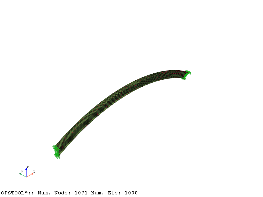
Visualization model geometry
opst.vis.pyvista.set_plot_props()
fig = opst.vis.pyvista.plot_model()
fig.show()
Model Mass and Gravity Loads. Because we have defined the material density, the mass matrix will be automatically computed by OpenSees when we create the elements. We can check the nodal masses by:
node_masses = opst.pre.get_node_mass()
Likewise, we can create gravity loads using the utility function, it will automatically extract the nodal masses and create the load pattern for gravity loads.
ops.timeSeries("Linear", 1)
ops.pattern("Plain", 1, 1)
opst.pre.create_gravity_load(direction="z", factor=-9.81)
Eigen Visulaization
fig = opst.vis.pyvista.plot_eigen(mode_tags=[1, 2], subplots=True)
fig.show()
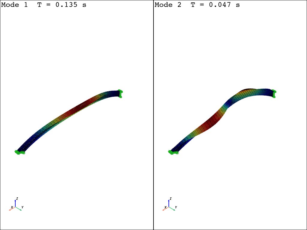
OPSTOOL™ :: Eigen data has been saved to G:\opstool\docs\.opstool.output/EigenData-Auto.zarr!
Gmsh model
You can find the Gmsh modeling instructions for this model here: Generating a shell model with the Gmsh Python API.
import gmsh
import numpy as np

filename = "I_beam"
# I-beam profile
wb = 0.2  # bottom flange width
wt = 0.3  # top flange width
h = 0.5  # web height
# Arch geometry
theta = np.pi / 6  # arch opening half-angle
L = 10.0  # chord length
R = L / 2 / np.sin(theta)  # arch radius
f = R - L / 2 / np.tan(theta)  # arch rise
gmsh.initialize()
gmsh.model.add(filename)
geom = gmsh.model.geo
lcar = 0.1  # characteristic mesh size density (will not be used)
bottom_points = [
    geom.addPoint(0, -wb / 2, -h / 2, lcar),
    geom.addPoint(0, 0, -h / 2, lcar),
    geom.addPoint(0, wb / 2, -h / 2, lcar),
]
top_points = [
    geom.addPoint(0, -wt / 2, h / 2, lcar),
    geom.addPoint(0, 0, h / 2, lcar),
    geom.addPoint(0, wt / 2, h / 2, lcar),
]
bottom_flange = [
    geom.addLine(bottom_points[0], bottom_points[1]),
    geom.addLine(bottom_points[1], bottom_points[2]),
]
web = [geom.addLine(bottom_points[1], top_points[1])]
top_flange = [
    geom.addLine(top_points[0], top_points[1]),
    geom.addLine(top_points[1], top_points[2]),
]
start_section = bottom_flange + web + top_flange
end_bottom_flange = []
end_top_flange = []
end_web = []
surfaces = []
for ini, end in zip([bottom_flange, web, top_flange], [end_bottom_flange, end_web, end_top_flange]):
    for l in ini:
        outDimTags = geom.revolve(
            [(1, l)],
            L / 2,
            0,
            -(R - f),
            0,
            1,
            0,
            2 * theta,
            numElements=[50],
            heights=[1.0],
        )
        end.append(outDimTags[0][1])
        surfaces.append(outDimTags[1][1])
        geom.synchronize()
end_section = end_bottom_flange + end_web + end_top_flange
Add a physical group. The name of the physical group is important for the subsequent conversion.
gmsh.model.add_physical_group(dim=1, tags=start_section, tag=1, name="start_section")
gmsh.model.add_physical_group(dim=1, tags=end_section, tag=2, name="end_section")

plane_tags = gmsh.model.get_entities(dim=2)
plane_tags = [tag[1] for tag in plane_tags]
gmsh.model.add_physical_group(dim=2, tags=plane_tags, tag=3, name="surfaces")
for quad mesh if does not work, try to use Recombine 2D in gmsh GUI you can find options in https://gmsh.info/doc/texinfo/gmsh.html#Mesh-options
gmsh.option.setNumber("Mesh.RecombineAll", 1)
gmsh.option.setNumber("Mesh.RecombinationAlgorithm", 2)
gmsh.option.setNumber("Mesh.Algorithm", 8)
gmsh.option.setNumber("Mesh.ElementOrder", 1)
gmsh.model.mesh.generate(dim=2)

gmsh.option.setNumber("Mesh.SaveAll", 1)
# gmsh.write(filename + ".msh")
# gmsh.fltk.run()  # uncomment to visualize the geometry
gmsh.finalize()
Total running time of the script: (0 minutes 2.262 seconds)